Microchannel coils for air-source heat pumps
Microchannel heat exchangers have seen increased application in air-to-water heat pumps due to offering significant charge reduction, compactness, lower air pressure drop, and consequentially, lower fan power consumption compared to traditional round tube-plate fin coils.
One of the key advantages of adopting microchannel coils is their low internal volume, resulting in low refrigerant charge and the ability to use flammable refrigerants like propane or ones of the A2L flammability class.
Known issues when using microchannel coil in heat pump applications are refrigerant-side maldistribution, which remarkably impacts performance, and coil operation under frosting conditions when frost cycle time shall be reduced in order to maintain the system performance (see “Methods of microchannel coils defrosting,” Kaltra, September 2016).
Besides the degradation of heat transfer, frost deposition on heat transfer surfaces results in several adverse effects such as blockage of airflow passages and increased pressure drop and fan power.
The recent parametric studies on microchannel coil operation under frosting conditions and consequential field tests performed by Kaltra figure out the best trade-off in air-source heat pump design based on microchannel heat exchangers.
Frost-Resistant Heat Pump Design
Frost growth usually occurs due to the moisture content of the air as well as the generally low operating conditions of evaporators. During the defrost cycle, the heat pump doesn’t provide heating and consumes additional energy. In comparison to finned tube heat exchangers, microchannel coils typically require somewhat more frequent defrost, making the task of defrosting optimization even more topical.
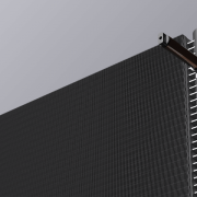
The time between defrosting cycles on a frosting coil can be increased with the use of a lower fin pitch, but this significantly lowers the heat transfer rate. In our experimental heat pump setup, we used a two-slab heat exchanger construction with a dehumidifying coil having a lower fin density located in front of the airflow and the second coil of high fin density. This design leads to a significant portion of the moisture to condense and collect on the front coil.
The amount of heat transfer in the front coil is limited, causing minor airflow temperature drop, limiting the amount of condensed moisture, and delaying the frost formation. A wide fin spacing of the front coil causes condensate formed on the fins to flow downward by gravity easily. Further heat transfer occurs as the airflow passes through the second coil.
The above design allows to significantly increase defrost intervals and reduce defrost time. The second coil – evaporator – will not be subjected to icing in almost all weather conditions except complete extreme.
Improving Refrigerant Distribution
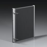
Even and uniform refrigerant distribution between multiport tubes of microchannel evaporator is a key for stable and efficient operation. Adopting the evaporator design with an integral distributor is crucial for reversible heat pumps and ensures their performance at partial loads (see “Optimization of refrigerant distribution for microchannel evaporators,” Kaltra, February 2020).
Given that proper condensate removal is only possible with vertically-oriented microchannel tubes, the heat exchanger arrangement of reversible heat pump must have manifolds installed on top and bottom, with preferable refrigerant inlet on the bottom.
Flash Gas Bypass
Flash gas bypass enhances the system’s efficiency by separating two-phase refrigerant flow from the expansion device into liquid refrigerant provided to the evaporator and vaporized refrigerant provided directly to the compressor. In a reversible heat pump with the dehumidifying coil, flash gas bypass shall be installed upstream of this coil. Experimental setup demonstrated that deploying a flash gas bypass gives about a 20-percent performance gain over conventional circuiting.
Coil Installation Angle
Reversible heat pumps operate in either direction to provide cooling or heating, employing a reversing valve to reverse the refrigerant flow. In heating mode, when the heat exchanger acts as an evaporator, condensate water must be effectively removed from the heat exchanger surface.
The installation angle of the heat exchanger impacts condensate behavior: In most cases, the coil can be installed vertically, while horizontal installation will lead to condensate retention. For high condensate volumes, optimum inclination angles are 15 to 25 degrees to vertical. It must also be noted that louvered fin design is far preferable for better condensate shedding compared to flat fins.
Hydrophobic Coating
To further mitigate frost accumulation on the coil surface, a hydrophobic coating can be applied to the exterior surface of the heat exchanger. This prevents performance degradation and delays frost accumulation and reduces the frost build-up rate. Frost that does form on the hydrophobic coating is generally weak and loose compared to frost formed on uncoated surfaces. The resultant effect is the shorter time required to defrost.
***
Despite some complexity of adopting microchannel heat exchangers in reversible air-source heat pumps, accurate system implementation offers considerable improvements over traditional systems featuring finned tube coils and significant energy savings for end customers, while the low refrigerant charge is an exciting, promising prospect in terms of environmental sustainability of next-generation heat pumps for residential and commercial market segments.
In sum, the advantages of a novel heat pump design are worthy of attention:
- Low refrigerant charge and associated environmental sustainability
- Lifted efficiency, less energy use
- Stable operation in winter conditions
- Low noise output