The effect of protective coatings on the thermal-hydraulic performance of MCHEs
Protective coatings, being widely used for protection against unfavorable environmental exposure of heat exchangers, have raised many questions concerning their influence on thermal performance of coils and increased air resistance.
***
Such effects were investigated by Kaltra, which performed field tests of microchannel heat exchangers with different coatings. Measured parameters included thermal conductance and airside pressure drop. Coils with electrophoretic epoxy resin coating – e-coating – and trivalent chromium process coating – TCP coating – were compared with bare, uncoated coils. The same measurements were repeated after 480-hour SWAAT tests on the coils, simulating operation under unfavorable environmental conditions. These measurements were conducted after cleaning of the coils.
The latter series of tests is of special interest because corrosion of heat exchangers not only weakens mechanical integrity — resulting in issues like tube pitting and fin material loss — but also degrades thermal-hydraulic performance.
Initial Tests
Fig. 1 and Fig. 2 show the results of the first set of measurements for brand-new microchannel coils — bare, e-coated, and one with TCP coating — representing thermal conductances and airside pressure drops, respectively.
Figure 1: Thermal conductance for new-built MCHEs
Figure 2: Thermal conductance for new-built MCHEs
At the same airflow rate, thermal conductance for the three MCHEs is not different from each other. Airside pressure drops of the bare coil and TCP-coated coil are virtually identical, and that of the e-coated coil is as much as 15% higher (for a fin pitch of 2.2mm used in tests). Measurement results indicate that the thin chromium conversion coating (≤3.0µm) has minimal impact on the coil’s thermal-hydraulic performance. E-coated coil with coating thicknesses of 12.5-50.0µm has reduced free flow area with an attendant increase in air velocity and an increased airside pressure drop, as observed from the experiment.
While this increased air velocity certainly raises the heat transfer coefficient for the e-coated coil, the non-metallic e-coating layer adds large thermal resistance to the fins. These counterbalancing influences on heat transfer result in rather small differences in the thermal conductance for the e-coated coil as compared with the other coils tested.
In order to properly compare the effect of the increased pressure drop of the e-coated heat exchanger on system efficiency, one must compare thermal conductance values at an equivalent fan power. The thermal conductance of the e-coated coil under those conditions is about 2% lower than that of the bare coil.
Post-Corrosion Tests
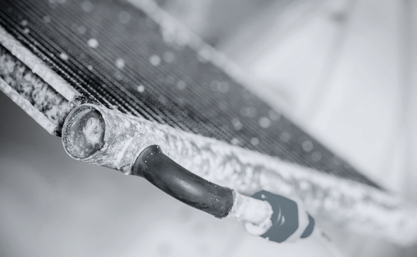
After the 480-hour SWAAT corrosion test, the bare coil exhibited severe deformation and significant loss of brazed joints. The TCP-coated coil also showed some deformation and joint loss, though to a lesser extent. In contrast, the e-coated coil demonstrated strong corrosion resistance, maintaining structural integrity throughout the test.
Thermal conductance of the three tested MCHEs before and after the corrosion tests is shown in Fig. 3 to 5. The thermal conductance of the bare coil reduced by approximately 70% after the corrosion test, due in large part to fin/tube debonding from corrosion of the brazed joints. Detached fins lose their effectiveness as heat transfer surface area, and even where fins do remain bonded, surface corrosion further degrades heat transfer performance.
Figure 3: Thermal conductance for bare coil before/after SWAAT test
Figure 4: Thermal conductance for TCP-coated coil before/after SWAAT test
Figure 5: Thermal conductance for e-coated coil before/after SWAAT test
For the TCP-coated heat exchanger, thermal conductance decreased by approximately 60% after the corrosion test (Fig. 4). Similar to the bare coil, this degradation is attributed to fin/tube debonding. Visual inspection showed that braze joint loss in the TCP-coated coil was about 15%, compared to 30% in the bare coil — likely contributing to the slightly better thermal performance of the TCP-coated coil after the corrosion test. These findings underscore the importance of protecting braze joints to maintain long-term thermal performance of MCHEs. Additionally, fin corrosion in the bare coil may have further exacerbated the reduction in thermal conductance.
By contrast, the e-coated coil showed only a small variation in thermal conductance (up to 2% at a frontal air velocity of 1.0m/s) after the corrosion test, which lies within the experimental uncertainty (Fig. 5). The e-coating proved resistant to corrosion under the SWAAT environment and maintained the thermal performance of the coil.
After the corrosion test under a frontal air velocity of about 2.0m/s, the air-side pressure drop of the bare coil increased as high as 25%, shown in Fig. 6. This is because of the fin deformation and changes in the surface condition of the coil due to the corrosion.
By comparison, the air-side pressure drop for the TCP-coated coil decreased up to 3% (Fig. 7), and the pressure drop for the e-coated coil decreased up to 6% after testing (Fig. 8). These more modest pressure drop reductions for the TCP-coated and e-coated coils, relative to the bare coil, are a result of little or no fin deformation on the coated coils.
Figure 6: Air resistance for bare coil before/after SWAAT test
Figure 7: Air resistance for TCP-coated coil before/after SWAAT test
Figure 8: Air resistance for e-coated coil before/after SWAAT test
Conclusion
This work studied the corrosion performance of three similar microchannel coils, bare, TCP-coated, and e-coated under an SWAAT corrosion test to examine their thermal-hydraulic performance pre- and post-exposure.
Pre-Corrosion Performance
It was found that, prior to corrosion testing, the e-coated coil had a more significant impact on thermal-hydraulic performance compared to the TCP-coated coil. More specifically, the e-coated coil showed a higher airside pressure drop compared to the uncoated coil at the same frontal velocity and a 2% lower thermal conductance compared to the bare coil when tested at the same fan power. In contrast, minimum deviations from the bare coil in both airside pressure drop and thermal conductance were observed for the TCP-coated coil.
Post-Corrosion Performance
After SWAAT, the bare coil exhibited extreme deformation along with the loss of brazed joints, and the airside pressure drop of this coil was increased by up to 25%, while its thermal conductance was decreased by about 75%. The TCP-coated coil also underwent some degree of deformation and joint loss but still maintained the original airside pressure drop with a large 60% loss in thermal conductance.
For both bare and TCP-coated coils, this decrease in thermal conductance is explained by the drastic loss of brazed joints caused by corrosion. On the contrary, the e-coated coil showed good corrosion resistance throughout the whole test and almost negligible changes in thermal-hydraulic performance. It means the e-coating will protect both structural integrity and thermal performance effectively for a coil under severe conditions, which indicates it as a robust choice for such applications where the structure is exposed to corrosive environments.
SWAAT Corrosion Test
Corrosion tests were conducted in full compliance with ASTM G85−19 (Standard Practice for Modified Salt Spray (Fog) Testing) Annex A3, seawater acidified test, cyclic (SWAAT), which covers and sets forth conditions for testing for specification purposes.
SWAAT evaluates the corrosion resistance of coated and uncoated metals and aluminum alloys when exposed to synthetic sea salt and humidity at a high temperature.
The apparatus required for salt spray (fog) testing consists of a fog chamber, a salt solution reservoir, a supply of suitably conditioned compressed air, one or more atomizing nozzles, specimen supports, provision for heating the chamber, and necessary means of control.
A synthetic sea salt solution is used for SWAAT. It consists of 42g of synthetic sea salt (in accordance with ASTM Practice D1141) per liter of solution, with the addition of 10mL of glacial acetic acid per liter of solution. The pH of the salt solution is adjusted between 2.8 and 3.0.
The temperature in the saturator tower is maintained at 47°C±1°C if the cabinet temperature is 35°C and 57°C±1°C if the cabinet temperature is 49°C. The temperature in the exposure zone of the salt spray chamber should suit the material being tested. For uncoated aluminum alloys, a temperature of 49°C is recommended for the exposure zone.
Although the humidity limits for optimum test conditions have not been determined, the results of an interlaboratory testing program indicate that it is necessary to operate under wet bottom conditions. This ensures that the interior of the box does not become dry, a condition that will decrease the corrosion rate.
The testing cabinet is equipped with a timing device set for the following cycle: a 30-minute spray followed by a 90-minute soak at above 98% relative humidity.

