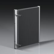
Refrigerant distribution in microchannel evaporator at multiport tube level
Previous studies have examined refrigerant distribution across tubes in microchannel evaporators. Various methods have been explored to minimize refrigerant maldistribution between tubes, including specialized inlet manifold designs with DX distributors, flash gas bypassing, coil geometry optimization, and refrigerant charge control.
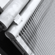
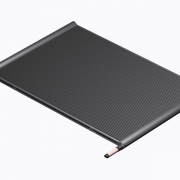
In addition to the factors considered in the above publications, uneven heat transfer is also a key contributor to refrigerant maldistribution. In fact, heat transfer irregularities occur not only between tubes but also among individual ports within a flat tube along the airflow direction, where the air temperature gradually decreases. A numerical investigation of maldistribution was carried out using a heat exchanger featuring 30-port microchannel tubes (32 mm width, 1.3 mm height) spaced 10 mm, with 2.4 mm pitch louvered fins. Refrigerant (R134a) with a quality of 0.2 was supplied to the bottom inlet manifold and injected into 40 vertically oriented 400mm length tubes for evaporation. Air and refrigerant inlet states are shown in Table 1.
|
AIR SIDE PARAMETERS |
REFRIGERANT SIDE PARAMETERS | ||
|---|---|---|---|
|
Dry-bulb temperature [°C] |
25.0 |
Inlet temperature [°C] |
10.0 |
|
Relative humidity [%rH] |
60 |
Superheat [°C] |
5.0 |
|
Air velocity [m/s] |
1.80 |
Quality/Mass |
0.20 |
|
Air pressure [kPa] |
97.25 |
Massflow [kg/h] |
0.15 |
Table 1: Air and refrigerant inlet states
Results
Measurements of refrigerant quality, refrigerant pressure drop, refrigerant and air temperatures, massflow rate, condensate formation, and heat transfer rate were conducted at the port level along the lengths of the microchannel tubes.
Refrigerant Side
The results indicate that refrigerant quality increases in the first ports along the airflow direction, particularly in the top half of the tubes (Fig. 1). This occurs because the air temperature decreases and the refrigerant massflow rate increases in the ports along the airflow direction.

Figure 1: Refrigerant quality vs. tube ports
Refrigerant temperatures gradually decrease along the airflow direction, starting at 23.5°C at the outlet of the first port, closely approaching the air inlet temperature of 25.0°C (Fig. 2). The length of the superheated region progressively shortens in the direction of airflow.

Figure 2: Refrigerant temperature vs. tube ports
The pressure drop behavior in microchannel tube ports (Fig. 3) differs between ports where full evaporation occurs and those with partial evaporation. In the frontal ports (01 to 15), the pressure drop of the refrigerant increases with rising refrigerant quality until it reaches approximately 0.85, after which it sharply declines. This behavior is observed even in superheated regions.

Figure 3: Refrigerant pressure drop across ports
The refrigerant massflow rate across the ports of the microchannel tube increases along the airflow direction. A gradual increase is observed for ports 1 to 15, followed by a rapid rise for ports 16 to 30 (Fig. 4). The primary cause of the uneven refrigerant mass distribution is the non-uniform heat transfer among the ports, which ultimately affects the distribution of refrigerant quality and pressure losses across the ports.
Figure 4: Massflow distribution across ports
For the ports in the front section of the microchannel tube, a longer superheated region corresponds to a lower refrigerant mass flow rate. In contrast, for the rear ports containing two-phase refrigerant, the refrigerant quality decreases sharply along the airflow direction.
Air Side
Figure 5 illustrates the air temperature distribution over the tube ports, primarily influenced by refrigerant temperature and heat exchange. The distribution of condensate water over the tube ports is presented in Figure 6.

Figure 5: Air temperature vs. tube ports

Figure 6: Condensate formation vs. tube ports
Heat Exchange
The heat exchange gradually increases for the frontal ports (1 to 15) and then sharply decreases for ports 16 to 30. The peak heat transfer observed in the middle ports, despite the decreasing temperature difference between the air and the refrigerant, is attributed to higher condensate formation rates on the airside. For ports 16 to 30, where full evaporation does not occur, both the temperature difference and condensate formation rate gradually decline, leading to a reduction in heat exchange.

Figure 7: Heat exchange across ports
***
Based on the present research, Kaltra modified the direct expansion (DX) distributors for its microchannel evaporators by adjusting the orientation of the distributor orifices toward the first ports in the airflow direction. This adjustment equalizes the mass flow across ports, thereby enhancing overall evaporation within the microchannel tube ports.